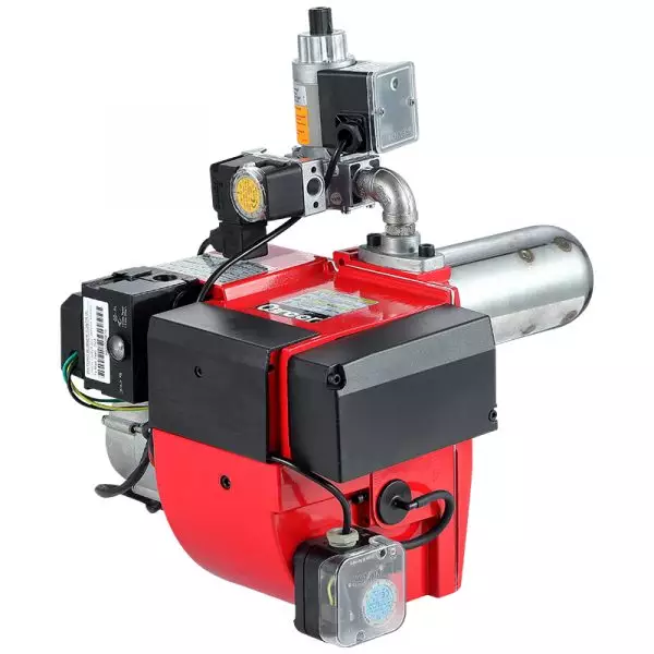
Industrial gas combustion requires more than reliable ignition. Fuel must reach the burner only when the combustion chamber, airflow, pressure conditions, and control sequence are suitable for firing. Modern gas burner systems therefore use multiple protective functions rather than relying on a single safety device.
Typical protection includes gas pressure switches, automatic safety shutoff valves, flame detectors, air-pressure monitoring, valve-proving functions, purge controls, and a burner management system (BMS). Together, these devices establish permissives for startup, supervise operation, and remove the fuel source when an unsafe condition occurs.
Safety Starts Before Fuel Reaches the Flame
A modern burner does not simply receive a start signal and open its gas valve. The fuel train first establishes whether the gas supply is within the required operating range.
Low- and high-gas-pressure switches can monitor abnormal supply conditions. A low-pressure fault can prevent stable combustion, while excessive pressure can create an overfiring or control problem. If the monitored condition falls outside the engineered limits, the safety circuit can prevent firing or initiate shutdown.
Automatic safety shutoff valves provide another layer. These valves are designed to stop fuel flow when their electrical safety circuit is de-energized. Industrial fuel trains may also incorporate two safety shutoff valves and a valve-proving arrangement that checks whether the valves provide the expected isolation before ignition.
Career Burner manufactures gas-fired burners across a 50–7000 kW capacity range and provides configurations intended for different industrial heating requirements. Consequently, the safety architecture surrounding a burner should be engineered around the actual burner and process rather than treated as a universal accessory.
How the Burner Management System Controls Ignition
The BMS acts as the sequencing and safety logic for many larger industrial burners. Its role is distinct from ordinary firing-rate control: the BMS determines whether conditions are safe enough to start, continue, or stop combustion.
Before ignition, the combustion chamber may undergo a controlled pre-purge. Combustion air is introduced to remove potentially hazardous residual fuel or combustible mixtures before ignition energy is applied. Airflow proving can be incorporated so that the control system does not proceed unless the required combustion-air condition has been established.
The ignition sequence then proceeds through defined stages. Depending on the burner design, ignition may establish a pilot flame before the main flame. The control system verifies the required conditions before permitting the relevant gas valves to open. If a required permissive is absent, the sequence stops rather than proceeding to uncontrolled fuel admission.
This sequencing is one reason gas burner systems are built around coordinated controls instead of isolated components. The safety logic connects pressure devices, airflow verification, valve status, ignition, and flame supervision into one controlled sequence.
Flame Detection Is the Critical Feedback Loop
Ignition alone does not prove that combustion is continuing safely. A flame detector provides feedback to confirm the presence of the expected flame.
Industrial flame supervision can use technologies such as UV or ionization detection, depending on the burner and application. The burner controller continuously evaluates the flame signal during operation. If the expected flame is lost, the safety system can de-energize the fuel safety shutoff valves and place the burner into a shutdown or lockout condition, depending on the engineered sequence.
That feedback loop addresses a fundamental combustion hazard: gas must not continue entering a combustion chamber when the intended flame is absent. The detector therefore functions as part of the protective system, rather than simply as an indicator for the operator.
Valve position feedback can provide another layer of verification. Proof-of-closure devices can confirm that a safety shutoff valve has reached its closed position before a subsequent purge or ignition sequence is permitted. Valve-proving systems can also test the integrity of the isolation arrangement for leakage.
Protection Continues During Normal Operation
Safety supervision does not end once the flame is established. Combustion equipment can encounter changing gas pressure, insufficient combustion air, excessive furnace temperature, emergency-stop activation, or control-system faults during operation.
Air-pressure switches or equivalent airflow-proving devices can therefore form part of the burner interlock circuit. If combustion air is no longer adequate, the safety system can interrupt firing rather than allow the burner to operate under an abnormal fuel-to-air condition. Industrial safety arrangements can also incorporate temperature limits and other process-specific interlocks.
The exact arrangement depends on the equipment, fuel, combustion chamber, jurisdiction, and applicable standards. NFPA publications, EN requirements, and industrial combustion standards address different aspects of burner and fuel-system safety, so engineering teams should establish the applicable requirements before specifying the final protection architecture.
Why Safety Architecture Must Match the Application
Not every industrial burner requires an identical collection of instruments. A small packaged burner and a large furnace installation can have substantially different fuel-train arrangements, control strategies, and process interlocks.
For example, custom gas burners may need safety logic coordinated with a particular furnace, dryer, boiler, thermal oxidizer, or other process. Fuel characteristics, firing capacity, combustion-air arrangement, chamber design, operating temperature, and shutdown philosophy can all influence the appropriate configuration.
Career Burner’s product range includes automatic, modulating, compact, heavy-duty, and low-NOx gas burner configurations. Its published product information also identifies natural gas, LPG, and various process gases among compatible fuel categories. Such variation reinforces the need to treat burner safety as part of the complete combustion-system design.
For custom gas burners, the practical objective is not to maximize the number of safety devices. It is to establish appropriate layers of prevention, detection, isolation, and controlled shutdown for the specific process.
Building Safety Into the Combustion Sequence
Modern industrial burner safety is in essence a coordinated system. Pressure supervision checks the fuel supply, purge and airflow controls establish safe preconditions, the BMS manages the ignition sequence, flame detection confirms combustion, and automatic shutoff valves provide rapid fuel isolation when required.
The most effective design comes from integrating these functions around the actual combustion process. For industrial operators evaluating a new burner or retrofit, the relevant question is not simply whether individual safety components are present, but whether they work together to prevent unsafe fuel admission and produce a predictable response to faults.
